Article on Insulation from ASM’s Heat Treating Progress.
Here is an article discussing construction and insulation of cryoprocessing equipment and commenting on vacuum insulation.
As Published in Heat Treating Progress
CRYOPROCESSING EQUIPMENT
Key functional elements and insulation type determine operating efficiency and equipment life.
by Jeffrey Levine, Ph.D.
Applied Cryogenics Inc. Waltham, Massachusetts
As published in the January, 2002 issue of Heat Treating Progress
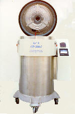
Figure 1. CP-200vi Cryoprocessor uses vacuum insulation
Cryogenic processing had its origins at the Watertown Arsenal Watertown, Mass. during World War II under the guidance of Clarence Zener, who would go on to develop the Zener diode among other advances in solid state physics. The method was straight forward. Steel cutting tools were immersed in liquid nitrogen for a brief period of time, removed from the liquid, allowed to warm up, and placed into service in the arsenal’s production lines. Occasionally tools would crack or chip as a result of the thermal shock associated with the rapid rate of cooling. Some tools also became brittle because of the newly formed, untempered martensite and chipped in service. Of the tools that survived this crude quenching, many exhibited dramatically enhanced service life.
During the 1960’s, cryogenic processing services started using multistage mechanical refrigerators in conjunction with insulated “cold boxes” to slowly cool tools to cryogenic temperatures. Rather than resorting to solid (tool) to liquid (liquid nitrogen) heat transfer, they utilized gas kinetics to remove the latent heat from the tooling. Not only did this gentler process avoid the problem of cracking during cool down, but it also yielded better wear resistance. This dependence of wear resistance upon cooling rate would later be quantified by Randall Barron. Post refrigeration tempering was also employed to toughen the fresh martensite and further improve the process.
With the growing acceptance of cryogenic processing today, several manufacturers now offer liquid nitrogen based processing equipment that attempts to mimic the slow cooling rates of mechanical refrigerators. While some are successful in this approach, others are still proponents of the solid-to liquid rapid cool down.
Key elements
A crucial element of any system that is designed to avoid thermal shock is a liquid-to-gas heat exchanger used in conjunction with a circulating fan. The heat exchanger contains the boiling liquid nitrogen (LN) and absorbs the thermal shock, while the fan circulates gaseous nitrogen over the heat exchanger (HE) and the payload to slowly remove the payload’s latent heat. Adding a programmable controller, an LN flow controlling solenoid valve, and a thermocouple to monitor gas temperature creates a servo system that permits the execution of predetermined time-temperature profiles. Additionally, introducing electric resistance heating elements in front of the circulator fan and upgrading to a dual output controller permit cooling and tempering in the same machine. While this approach is simple enough, some equipment departs from these essential principles and can produce disappointing results.
Some types of equipment do not incorporate an HE and circulating fan, but simply provide a spray bar to rain down a fine mist of LN droplets on steel and carbide tooling having stress concentrations at their sharp edges. In practice, it’s not clear how fine this mist must be to avoid rapid cooling of the surface of the edges of such tooling while the core remains warm. This results in contraction of the surface with the generation of transient tensile stresses; chipping and cracking may follow.
In another process approach, an insulated vessel containing the payload is slowly flooded. Theoretically, as the LN level rises slowly to envelop successively higher levels of tooling, parts above the liquid will have time to cool down before the liquid actually hits, thereby limiting the shock. Unfortunately, this scenario ignores two physical realities. The temperature gradient above a quiescent pool of LN is very steep and the rate of heat transfer from a warm solid to LN is orders of magnitude ‘greater than that between the same solid and gaseous LN at the same temperature as the liquid. This modified “dip” technique should be avoided.
Hybrid Systems
In an attempt to reduce LN consumption, hybrid systems that employ mechanical refrigeration with an LN assist are sometimes used. In principle this is a reasonable approach; its implementation, however, should be carefully scrutinized. The mechanical refrigerator component must provide a sufficient Btu removal rate to transfer out latent heat rapidly enough to reduce the temperature in the time required by the programmable controller. Larger payloads will require a greater Btu removal rate than a small payload running under control of the same program. Here, simply monitoring the chamber gas temperature may not ensure that the payload is getting cold. An underpowered mechanical refrigerator may have enough capacity to cool a thermocouple, especially if it is located near the expansion coil, but not enough to cool a large mass of steel. Under this condition, when the LN assist kicks in to take the load down further, thermal shock becomes a risk. In effect, the controller thinks the payload is colder than it really is and unleashes enough LN to rapidly achieve a larger temperature drop than intended for a given time interval. Once again, thermal shock is a potential problem.
From a purely practical point of view, hybrid systems may combine the worst of both worlds. Not only is a supply of LN needed, but one must also maintain refrigeration compressors that make repetitive, deep temperature descents. These compressors work less hard and last longer if they are required to merely maintain a low temperature in an insulated chamber, into which relatively small masses are occasionally added. A good example is a biological tissue storage refrigerator. Here, cryoprocessor service is very severe, requiring heavy-duty equipment to yield reliable service.
Over time, the principles of cryogenic engineering have been integrated into well-developed industrial practices and devices
To date, however, these principles have not been fully utilized by equipment manufacturers. The typical machine, even those designed to avoid thermal shock, is basically a modified tempering oven with ceramic insulation replaced by polyurethane foam. The engineering objective in designing an efficient cryoprocessor chamber is to minimize heat gain from the ambient surroundings. Such heat gains must be offset by LN consumption, which is expensive when compared to electricity or natural gas used for heating.
Considering economics
Design of an economical cryogenic system requires techniques not normally drawn upon in heating applications. Merely injecting foam insulation into the hollow walls of a tempering oven won’t do the trick. Any solid insulation is subject to failure by means of thermal cycling fatigue. When the inside of the chamber gets cold, the inner layer of insulation starts to contract while the outer layer of insulation remains near room temperature. Differential contraction of the insulating mass leads to internal stresses.
In machines that also temper, the stress distribution gets reversed. Repeating this cycling many times causes the insulation to fatigue, crack, and possibly crumble. Deteriorating insulation leads to increased LN consumption and also to thermal gradients within the processor. Polyurethane insulation is rated for a maximum operating temperature of 110C (225F) and, unfortunately, using it against the inner chamber wall, which reaches 150C (300F) and higher, results in slow deterioration.
Typical tempering ovens and typical cryoprocessors are constructed of thick steel members welded together to ensure structural strength. Consider the heat transport consequences of this approach. The outer walls of the device interact thermally with the gasketed surface against which a door closes. In turn, the gasketed surface interacts with the chamber interior. During a cooling cycle, ambient room heat is absorbed by the outer walls. It is, in effect, a giant heat absorber immersed in an infinite heat source, the atmosphere. This heat travels through the gasketed surface into the inner walls, which act as a radiator. The rate of heat conduction is proportional to the cross sectional area of the members; the thicker the steel, the more severe this problem becomes. This so called “heat bridge” results in LN consumption to offset these gains. The typical cryoprocessor door is also a heat bridge and contributes about as much heat gain as that of the body of the machine. Other heat bridges, of less importance, would be fan shaft penetrations and even LN supply pipes.
Similarly, the same massive steel members that contribute to ambient heat gain also contain latent heat that must be removed with that of the payload to the tune of about 0.251/lb. Unfortunately, this is strictly operating overhead. Although impressive to view, a cryoprocessor built like an Ml tank has substantial operating cost associated with it.
Insulating via vacuum
Cryogenics engineers have confronted these problems and provided diverse solutions. Principal among these is the concept of vacuum insulation. Instead of relying upon the insulating value of trapped air pockets as in solid insulators, vacuum insulation relies on nothing because there is no heat conduction or convection across a vacuum. The third possible transport mechanism, thermal radiation, can be mitigated by the insertion of an electromagnetic radiation reflector (aluminum foil) in the vacuum.
Naturally, the vacuum must be contained in something. This is typically a pair of concentric cylinders of nearly equal diameters.
These are welded together around the perimeter of one set of circular ends with each opposite end capped with its own circular plate displaced slightly in the axial direction so that they don’t touch. Alternate layers of aluminum foil and fiberglass cloth fill the annular space between the cylinders which is evacuated to about 10 torr. Essentially an industrial strength thermos bottle, it is nearly perfect insulation.
Fig. 2 – Liquid nitrogen consumption is directly proportional to the weight of the steel payload. T is a parameter related to ramp and dwell times in Applied Cryogenics’ CP-2OOvi.
In this design, the major mode of heat gain is via solid conduction from the outer cylinder through the junction between inner and outer cylinders and can be mitigated by careful design. Material thickness is intentionally kept to a minimum. The hoop stress resulting from the pressure differential between the evacuated region and the outside world is accommodated by the cylindrical geometry. The payload weight is supported at the junction between the inner and outer cylinders so that no support members, which would be heat bridges, are required. Additionally, there is no solid insulation to fatigue or slowly burn up; the non-payload is at a minimum. Here, vacuum insulation provides an example of less really being more. Less mass means less wasted LN which means more operating efficiency. Less solid insulation (essentially no solid insulation) means less heat gain and no degradation of thermal performance. This translates into greater operating efficiency and more net operating profit.
A pertinent numerical example compares the heat gain of a 150 mm (6 in.) slab of foam insulation to vacuum insulation containing reflective layers. With each maintaining a temperature difference of 220C (400F) across their respective surfaces, the foam passes 15.3 Btu/hrft while the vacuum passes 0.0080 Btu/hrft. Compared to the foam, the vacuum is more than a 1900-fold improvement, is more durable, and takes up considerably less space.
Reference: 1. “Cryogenic Treatment of AISIT8 and C1045 Steels,” by Randall F. Barron, Advances in Cryogenic Engineering, Vol. 26, Plenum Press Inc., 1980.
For more information on cryogenics go to http://www.cryogenicsociety.org